
Freeware 3D Printable Fader Caps & More
Just had a really nice chat with a Make Magazine editor who’s also into synth DIY and made these cool projects:
https://www.printables.com/model/725654-behringer-2600-illuminated-sliders
https://www.printables.com/model/725587-diy-19-rack-mount-brackets
Litte excursion for starters
Spring 2022: I am super stoked to see the master player Pedro Eustache on tour with an instrument which I had the pleasure to modify! Pedro had approached me with an interest in modifying a Behringer 2600 for him, and the process itself was extremely fun! Now, in early spring Pedro toured his custom 2600 with Hans Zimmer and band, and when Behringer got wind of it, they did this interview with Pedro where he shows the synthesizer and some of my mods, concluding that he “couldn’t do what I do without it” – wow! He even played it in the official performance video of the Oscar-winning “Dune” song.
Here’s what that modified beast looks like: Filter overdrive, 6db and 12db filter, master cv, master gate, eswitch mod and selectable fx programs and more…

Playlist of different mods
https://soundcloud.com/uibkmedan/sets/b2600-modifications
As for modifications, I’ll stick to my own findings, “commonly-known” material and include some points from of a list of great suggestions given by KSS in the Mod Wiggler forum. There are many ace findings and descriptions in the context of TTSH builds, yet I would deem it inappropriate to “milk” these without explicit consent. As for sonic nerd-out endeavours aimed at changing the basic tonal characteristics of this synth, I have a section “quest fro vintage sound” at the very bottom of this page.
On my unit I did a couple of crazy/cool things like:
- Master CV insert jack socket (between internal CV converter and all KBD CV sockets)
- VCF input mixer output socket
- -6db/-12db filter outputs of the 4072 type, prewired to the preamp input
- insert jack socket for the eswitch clock
- manual interrupt button for eswitch clock (manually stops toggling)
- manual fx type selector (delay, short delay, reverb)
- direct low frequency noise output prewired to Lag Generator input (for even lower noise/secondary noise modulation path)
- ADSR gate input to TRG input normal lug (for saving a multiple)
- envelope declicking
Great ARP Resource: https://github.com/CreativeInquiry/ARP-2600
ARP Submodule schematics: http://www.till.com/arptech/modmain.htm
Fair use and support:
The information gathered on this page is for fair use only. This is not because I find my stuff so great that I am worried about being ripped off – this page is for synth/DIY enthusiasts and the work put in here built on trust and enthusiasm. If you lack the technical skills and hire someone to mod your 2600 based on the info here, great! If you mod Behringer 2600s for commerical use and base your mods on the info here, you donate 10% of your profit per unit after the second unit sold to any of the organizations in the following list: https://drlizdobson.wpcomstaging.com/2018/02/18/feministsoundcollectives/. If you like these mods and want to support this page, donate any amount you see fit to any of the collectives/organizations in the same list.
PCB REVISIONS
While modding another XMAS for the excellent Pedro Eustache, who does amazing things with this machine and his wind controllers, I noticed Behringer changed PCB to green solder masks (like you find them on their newer machines such as the RD9 and RD8MKII). Apart from that I didn’t notice any changes in terms of setup/parts.

Trimmers and sound adjustments
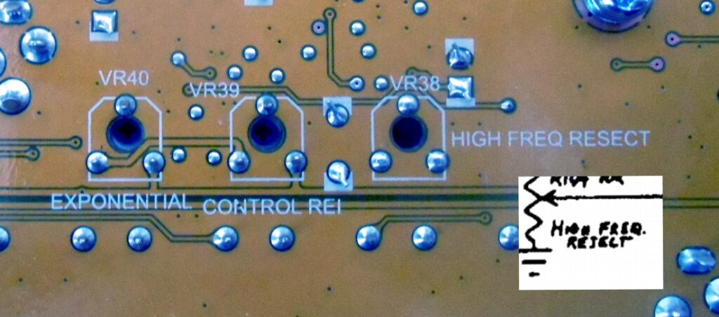
Robert Smedberg at Gearspace has mapped the trimmers and transferred calibration info form the Arp service manual. He kindly agreed to have this shared, in case someone needs calibrating. UPDATE: turns out there are some glitches in Robert’s PDF, so here’s a picture I did in reference to the PCB. Also NB that VCA High Frequency Reject and NOISE Level trimmers are not populated on the Behringer. Calibration takes patience and practice, especially tuning VCO tracking, so if you think you absolutely need to ccalibrate, be careful and always turn very gently!
Changing LED colours
spaceboy at gearspace has kindly agreed to share info on how to change the colour of the LEDs should you wish to do that. Check these posts, which describe how to change LEDs on the Xmas tree version to an all-amber appearance: https://gearspace.com/board/showpost.php?p=15422068&postcount=6713 and https://gearspace.com/board/showpost.php?p=15426119&postcount=6723.
By the way, the sliders used seem to be compatible with Bourns PTL.
MODIFICATIONS
Apologies for not providing any further updates/ or pending mod descriptions for this project any longer. I describe many mods here (more than the classic mods for the original), including mistakes and spelling glitches, and feel I rather want to spend time on other synth modding/development projects.
1V/OCT CV FROM CPU
The internal midi interface of the Behringer 2600 offers two 1V/Oct lines for duophonic play. The signal form the CPU (an ARM GD32F510) is amplified and filtered at ICs 18 and 26 for the “KBD CV” line and ICs 17 and 25 for the “Second Voice” line.
The inbuilt portamento is done software with with analogue control (on/off, mom, time). I personally find the lower portamento range has some headroom for improvement in that you move from nothing to just a bit too much too quickly. The jack sockets for portamento on and interval latch on the back of the 2600 are meant for use with footswitches, yet you can creatively “misuse” this. When plugging a cable, the tip carries 3,3V, which, when grounded, engages portamento/interval latch. So, when using an s-trigger converter (for instance the strig cable offered by Doepfer), you can sequence porta on/off and interval latch (I didn’t test with the doepfer but just pulled the cable tip to ground manually).
MASTER CV INPUT MOD (tested, works well): If you want to sequence the 2600 externally via CV, each VCO needs a dedicated CV input, which, when played monophonically, eats up a multiple and three extra cables. If you want to keep the flexibility of dedicated CV per VCO but also make use of quick and simple patching, you can easily insert a “MASTER CV IN” that breaks the connection from the internal midi converter and all “KBD CV” sockets. Simply lift R408 (100ohms) and wire the top terminal (leading to IC17) via a 100ohn resistor to the normal lug of a switched jack socket. The tip lug of your new socket goes to the lower PCB terminal for R408. The ground lug of your new CV in socket must be on ground – just use any ground lugs of the existing jack sockets.

MASTER GATE INPUT
Sounds maybe dumb for starters, but why would I want a Master GATE in when I have so many different gate and trigger inputs anyways? Dumb answer: because you can and because it makes life easier. When using the 2600 with an external GATE source that does not deliver moire than +5Volts you’re in a bit of a pickle since your ADSR won’t fire (see AR and ADSR sections further down). The level of your AR (typically used on the VCA) will also be lower than as used per the 2600’s internal midi converter). So, for doing a very straightforward “I just want easy gate without bazillion multiples or env retrigger stuff”, do this…

Around the GATE out and TRG out jack sockets on the left you find two NPN and PNP transistor switch setups. A 3,3v blip from the CPU (passing a 1k resistor) engages these switches, which then fire off a +10v gate and a +14v trigger. Wire up your MASTER GATE input socket as follows: diode from new input soccket tip lug to 1k resistor, which then is connected to the base of the NPN transistor. You need to do this for gate (T117) and trigger (T96) each, so two diodes-followed-by-resistor leading from your tip lug. Also clip voltages exceeding 3,3v (there’s only a 1k resistor between your new input and the CPU pins, so better stay safe). You can do this easily by writing another diode from your jack socket tip lug to the bottom terminal of C66 (cathode facing C66 bottom terminal). Checked this setup with different +5v gates and worked like a charm!
VCOs
VCOs are as per 4027-1 schematic. I need to trace more, but some parts are mapped in the pictures. All pp-amps used here are LM4580. Sync mod seems to be like Odyssey-derived classic suggestions with an NPP and a FET. At the moment, I don’t have big modding plans for these but might be interested in testing keysync (VCO reset on gate-on) at one point.


Cruder VCO synchronization: this is ilicit, forbiden and obscene, so don’t d it! In the follwoing audio demos, I just connected an additional input via an 68k resistor to the middle pin of the sync switch for VCO2 and VCO3. Sounds very crude, no? 😉
VCFs
Notable differences between ARP schematics and the layout on the 2600 is the option to use SMD or through-hole filter capacitors and the LM4580 op-amps replacing LM301. In the 4012 type, the AD3958 dual FET is replaced by two single FETs, T15 and T16 (each labelled “XY”). Moreover, in the Behringer the filter input signals are actively mixed.
Input signals are summed via R301-105 and pass an inverting amplifier (IC 20-B), are inverted again at IC20-A and passed through to the 4012 type via R144 (44k) and to the 4072 type via R172 (44k). FC CV is summed and inverted at IC21-B, and inverted again at IC21-A. For the 4072 type, FC CV then passes IC22-B (=ARP Z2A). IC11-B is inactive.


The filter type select switch toggles between output/feedback path PINs as equivalent to terminals “2” and “5” on ARP picture below:

The filter type not presently selected is still active as signal input and FC CV are always present on both. The output of the filter type not presently selected is active too (can be tapped at IC11, PIN1 for 4012 and IC22, PIN1 for 4072) but at zero resonance.
Accessing both filter types simultaneously (nope): Since resonance control is shared, an independent setup would require decoupling the type select switch and adding a sub circuit that duplicates the setup of R161, C62, and R160 as in the ARP schematic above. Yet, this would still mean that signal inputs and frequency CV in are identical on both types. The latter could be changed by inserting switched jack sockets by means of which one can break the internal signal flow, yet overall this seems too much effort for little gain.
Pre-filter overdrive mod: Driving both filter types with a hotter input mix signal can easily be done by lowering the value of R191 (74k), which is located between IC20-B and IC20-A. At the moment I prefer a switch for this (over a pot ) that roughly halves the value of R191. When all VCOs are cranked up, you get some crunch without tearing your ears off, however. My impression is that the 4012-type retains its “woody” characteristic for longer when overdriven, while the 4072-type starts sounding clippy earlier.
Eventually, I settled on a lazy/easy version of that mod. I tap the VCO mix output post-IC20 (see box labelled “4012 filter in” on pic above) and feed this via a 20k resistor and a 1uf cap to VCF mixer input 5 (jack socket, normal lug). I cut the trace between noise generator and the normal lug of the jack socket, so I can just pull up that slider for driving my VCO mix harder, and if I want noise on that slider, I just patch that connection up. Sounds like…:
Direct filter input mix output: the sum of all signals going into the filter is buffered by an opamp, so you tap this for a mix out (IC20-A) and/or even an inverted mix out (IC20-B). Since I had an inverting opamp wired up already, I just tapped the mix at IC20-B out pin and fed it via a 1k resistor and a 1uf capacitor to an output socket. This is an easy and super helpful mod for signal feedback/boost, for “inserting” and external filter and for creating different filter responses through mixing (i.e. Model D highpass trick).
The 1uf AC coupling cap is beneficial when feeding the mix signal back into itself since here since it clears out DC voltage, which actually results in less “mush” when you feed back the mix out to VCF inputs 4 or 5. (On the Behringer AC coupling caps are used on inputs 1-3.)
And some more recordings of how simple waveforms sound when you feed back the VCF mix into itself.
Resonance level loss compensation (tested, works): Background: some filter lose level on high resonance, and nifty engineers like Yusynth, Émilie Gilett and others offer solutions for compensating this. The trick is to tap the resonance slider and mix an amplified version of this signal to the final filter output – the more resonance, the more additional signal… As I yet feel reluctant to drill additional holes into the chassis, my solution is to route the level compensation signal to the VCA IN2 slider. This breaks the internal connection to the ring modulator, but since that one has a dedicated output socket, nothing is lost.
How to do this: tap the wiper of the resonance slider (at the filter type switch, see pic below), and feed that signal into an inverting it op-amp (74k at -in and 47k feedback resistor), then feed this into the normal lug of the VCA IN2 socket via a 1k resistor. Break the internal connection between the normal lug and ring mod output by cutting the trace leading to the normal lug (see pic). If you don’t use VCA IN2, your opamp buffer needs to be non-inverting (signals into VCA IN2 are inverted, so you need to invert in the above case to end up with the correct signal polarity). NB: the VCF output socket remains unaffected by this- if you wanted that, you’d need a switch/jumper for com on/off and sum your signals differently.


FILTER RESPONSE MODIFICATIONS FOR THE 4072 TYPE
-6db and -12DB OUTPUTs for the 4072 type: tap the pole outputs and send the signal(s) as follows: 100nf capacitor, then positive gain amplifier with 15K resistor at input and 100K resistor at feedback path. The AC coupling capacitor at the amp input is actually very helpful in limiting resonance screech on -6b/-12db modes. Protect the opamp output in good 2600 fashion with a 1k resistor. Then either use a separate output socket or rewire VCA IN2. Here’s how it sounds:
Pole outputs can be tapped as per schematic here: http://www.till.com/arptech/pdf/4072.pdf. Simply tap at junction C1-R1 for Stage1, junction C2-R6 for Stage2, and/or junction C3-R11 for Stage 3. Note that part designations refer to the linked schematic, not the Behri PCB!
By the way, you can easily create different filter types by pole mixing: use -12db out and -24db out for bandpas, for instance…
VCA
the VCA circuit on the Behringer shows a couple of deviations from the original implementation. A first would be that half a TL072 (IC23-B) is used in lieu of an LM301 opamp. Most notably, the High Frequency Reject trimmer (labelled “High Frequency Resect” on the Behringer) and its surrounding circuitry (Behringer R364, C206, C208) are not populated. A third notable difference is that we see a 470nf capacitor AC coupling VCA input 1. The latter block out DC voltage in the input signal that played a larger part in the notorious “VCA thump” of the ARP. VCA input 2 is not AC coupled.

VCA INPUT BOOST: finally got round to testing a bit more in the VCA area and found that a very fruitful and easy way to tip the 2600 towards more “bite” is to drive the VCA input(s) harder. While pre-filter overdrive can sound clippy in a not so neat way (especially on the 4072 VCF), pre-VCA drive is nicer in my opinion. Apart from introducing overtones, it also squashes the signal a bit – snappy sounds sound more compressed, as if there was a bit of a hold stage in the ADSR, but all of this is a matter of taste in the end.
If you want to drive VCA IN1 harder, reduce R447 (100k) to something between 68k and 50k (I wired a 150k resistor across). If you want to drive VCA IN2 harder, do the same for R448.

First half of that clip = normal VCA in, second half = driven harder. Both parts are kept at approximately the same level to bypass louder=cooler effects. As you can hear, amping is quite overdone in the second half but the compression effect and increased upper frequencies are also present when driven more subtly.
VCA THUMP: while the entire signal flow in the ARP was DC coupled, the Behringer sports a couple of capacitors blocking out DC signals, so you don’t get weird thumping sounds and/or damage your speakers. If you want to have that thump, for whatever reason, however, simply plug your FCV out to an inverter and the inverter output to VCA IN2 (you need the additional inversion since VCA IN2 inverts the signal polarity). Pull the VCA expo control up and thump away… NB since the VCF input mixer has DC blocking caps on inputs 1-3, you want to patch your square waves (rich in DC voltage) into VCF mixer inputs 4-5. And yes, on sufficient levels, this will damage your speakers.
ADSR and AR
Triggering/gating ADSR and AR independently: The Behringer is different to the ARP in that you can trigger/gate the ADSR and AR independently. This means, apart from the timing capacitor (spped switch), this is a modification we get ex factory. Since the setup is potentially confusinge, here’s a quick description:

Set switch labelled “1” to upper position. Send gate (+5V or higher) to socket labelled “2” – this engages the AR. For engaging ADSR, you need to send another gate to sockets labelled “3” and “4” simultaneously (use a multiple or stackable). This second gate needs to be +5V or higher. Confused myself here for a bit, since this is quite different on the ARP/TTSH but B2660 quickstart guide (page 17) confirms gate in threshold of +4v and trg in threshold of +5v.


AMS Synths pointed out in the comment section here that also the AR circuit was adjusted to have a faster attack time, a mod done by using a transistor instead of a diode. (BTW it’s great that Robert Keeble is pointing out technical aspects more concretely.)
Boosting AR Level with external gates of +5V (not needed when using MASTER GATE modifcation): When gated by the pushbutton or the internal SH clock, the AR produces a higher level than when gated externally by +5V gates. This is because the AR is not a proper “envelope” but a lag processor that slews the incoming gate voltage. In the following clip you first hear internal gate, then an external 5V gate, then a boosted gate with AR controlling VCA volume:
If you use +5V more often than +10V gates, this might be a mod for you. No trace cutting is needed and there is no interference with the internal wiring, i.e. gates by pushbutton and S&H remain the same.

An external gate at AR GATE IN opens Q1, which then passes through +10V to the base of T82 (T82 is the previously mentioned AR timing mod). D1 protects Q1 from negative voltage, R2 is for protection against shorts (maybe not needed). D2 makes sure your added AR boost does not interfere with internal gates. On the following picture points for soldering on the back of the PCB are labelled:

Alternatively, you can use external gain boosters (Ladik Gain Up, or Doepfer 183-4) or check out my utility module suggestion on the bottom of the page.
Normal ADSR Gate in socket to TRG in socket: this saves you a multiple when triggering/gating the ADSR. Wire the tip lug of ADSR GATE IN to the normal lug of TRG in via a diode (cathode to normal lug of TRG in). Plugging a cable into TRG in breaks this connection.
ADSR TRIGGER THRESHOLD: Should your external sequencer/synth not deliver the necessary voltage to trigger the ADSR of the 2600s, you can lower the voltage threshold for triggering by reducing the value of R427 (120K, equivalent of ARP R20).
Fix envelope clicks: This may be nitpicking, but the envs are clicky – again (again, as in this is not a Behringer first). Yes, this is related to more aspects than just the envs, but these also click on my Dominion1 and Neutron, so the first mod I did was a 220nf between AR jack socket tip lug and ground. For location see reso level compensation picture above. [Might do 47nf-100nf on ADSR also.]
LFO

No mods planned, but the LFO can retrigger when trigger switch is set to multi (thanks @TomNoise for the correction!), and a potential mod could be to have a retrigger in jack connected to the corresonding pin of the trigger switch. In the LFO circuit itself, T103 would be the respective FET responsible for retrigger.
RINGMOD

No mods planned for this one.
NOISE

Not really any mods planned here for the noise circuit itself.
LF Noise to LAG PROCESSOR IN: KSS mentioned having modded some ARPS with direct LF noise outputs, which is a neat way of having a dedicated modulation source available if you use white noise for audio purposes. (Think using the SH regardless of noise level fader setting).
Since I don’t feel like drilling holes yet, I just broke the normal connection between Envelope Follower out and LAG in and rewired LF noise from the Noise Colour Fader via a 1K resistor to the normal lug of LAG in. With lag slider fully left, you have LF noise and with increasing lag, you filter the noise even down more. Gives you a secondary noise modulation/audio source without much effort!

Here’s some demos of LF out into LAG
S&H
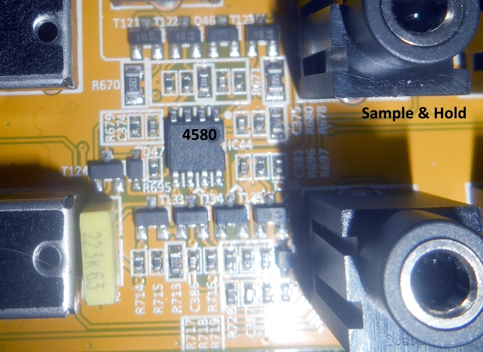

CV for S&H CLOCK SPEED modification (general suggestion by KSS): I installed a CV in socket for controlling the speed of the SH clock. Wire a 15k resistor to the collector of T99 and a diode from ground to the junction of your input socket tip lug and that 15k resistor to clip any incoming negative voltage. [15k impedance is low – eurorack “standard” would be 100k), yet T99 receives 0-15v via a 40k resistor, R534, so unless you send in some 100volts, this should be okay. Belts and braces would be using an opamp buffer, I assume.]
E-SWITCH
The electric switch is set up as per schematic, so I just describe the classic ext clock mod here. This mod is not new and comes up in many discussions, and while it is straightforwar, it opens up a whole lot of additional possibilities.
The electric switch on the 2600 is a useful circuit for all sorts of applications, from clocked distribution of signals to creating a sub oscillator, and more. The switch is bidirectional, i.e. you can use it to toggle between two signals present at “A” and “B”, which are then sent out at “C” in an alternating fashion, or you can use “C” as an input, which is then alternatingly sent out of “A” and “B”. The toggle control of that switch is the S&H clock, yet, unlike the S&H, the E-SWICTH toggle is not affected when plugging an external clock source into the EXT CLK IN.
Fortunately, you can easily DIY this and rewire things so that the E-SWITCH toggle can be externally clocked. You need to cut one trace as marked on the first image below (NB your cut needs to the left of the tiny circle in the trace, otherwise you cut the internal clock to SH connection!). Then connect terminal “MOD X1” on the first picture with wire to the terminal “MOD X2” on the second picture.


Alternatively, you can also wire up a dedicated E-SWITCH clock input (you’d need to drill & place a socket for the latter), so that you can clock the S&H and the E-SWITCH independently with external clock sources. In this case, cut trace as shown and wire normal pin lug of EXT CLK IN to a switched socket (normal lug), which then (tip lug) goes to the “MOD X2” point. The existing setup around C383 converts gates and longer pulses into short trigger pulses, so no extra circuitry is needed. Once I decided on a layout for additional controls, this will be the first hole to be drilled on mine.
“Lazy” version of this mod (since you do not need to lead wire around from the back to the front of the PCB) is as follows:

Cut the trace as in the other version, but since we’re bypassing two resistors on the front of the PCB wire using the through VIA solder point, we need to add them to the back. Now, here’s something weird: as per ARP schematic, we’d need to wire the Clock socket lug to the junction of a 10k and a 22k resistor, with the 22k wired to ground and the 10k to our re-entry point (junction Behringer R708-C383). On the Behringer, however, the values of these resistors are slightly lower, and with the extra setup, internal clock signal is too low to get the E-Switch going. I tried different values and ended up simply wiring a 1k resistor between the tip lug of the EXT CLK socket and the junction of R708-C383. Tested and working well with internal clock and VCO1 pulse wave into EXT CLK IN.
Mixer (post VCA)
The 2->1 mixer between VCA and Reverb unit is, like on the ARP, built around an inverting amplifier (IC23-A, see VCA section picture) and a couple of faders and resistors. The faders have an insert output, which makes them handy for attenuating modulation sources, but you can quickly run out of the pair. Now, although there is an insert point after the mixer, any signal plugged in there does not pass through the reverb, so an additional mixer input or more make sense (as KSS suggests). Wiring this up ius very easy: connect a jack socket via a 100k resistor to the bottom terminal of R236 (or the corresponding via on the back of the PCB). Plug your VCA output to that socket and have both attenuators freely available.
DIGITAL FX (XMAS-TREE VERSION)
The digital spring reverb is based on a Coolaudio V1000 Multi-FX DSP chip and a Coolaudio V4220M for AD/DA-conversion. Since the V1000 offers several pre-programmed FX algorithms that can be addressed by external voltage, you can do a couple of nifty things without much effort.

Reverb Spring Rattle Mod: This one is silly but fun. Spring reverb tanks rattle when shaken, and using this for musical effects has become some stock element in “rock and roll” gestures (high on the list with keytar banging and wiggling your fingers when playing vibrato per aftertouch). Some FX boxes, like the Vermona Retroverb Lancet, even offer options to do this rattle by the push of a button, and this mod here emulates that. Wire a momentary-on pushbutton between IC6, PIN7 and a 1k resistor. The other terminal of your resistor goes to ground. When you push the button, the voltage on PIN7 of IC6 is pulled below +2V, causing the FX DSP change from program “Spring3b” to program “Chamber2” (which is a 7-second church reverb). If you push that button quickly the resulting FX sound is at least a bit reminiscent of rattling springs.
FX Program Rewiring: As per V1000 datasheet, you have 16 internal FX programs (i.e. algos) available, including reverbs, delays, phaser, flanger, and chorus. Programs are selected by a simple on/off-state combination of four IC pins (see pic above – green = “prog0”, blue =”prog 3”). On/off, in this case means if a voltage between 0 and +0.3V is present at the pin, it’s off, and if a voltage between +2V and +5V is present, it’s on. In the case of the spring reverb prewired on the 2600, this would be, from “blue” to “green” – off, on, on, on, and accordingly, you see IC6, PINS 7, 6, and 5 connected via 10k resistors to the top terminal of L4, which carries around +4.7V, while IC6, PIN8 is wired to ground via a 47ohm resistor. Rearranging your presets is as easy as removing R80, R81, R84, and R85, and reconnecting the program pins according to which FX Program you would like to have. Keep a 10k resistor between each ON pin and L4, and a 47ohm/100ohm resistor beween OFF and ground. Suggestion: use a DIP switch or, if you want to be fancy, a switching IC. Punk suggestion: route an LFO (via a 1k resistor) to any of the program Pins. For available programs, see V1000 datasheet, page 4.
Here’s some delay, chorus and reverb switching:
UTILITY MODULE FOR ACCOMMDATING FURTHER USEFUL MODS
If you use a modular synth and have some space in your rack, here are some utility module suggestions I find helpful as 2600 aides.

KSS’s suggestion of an additional comparator as a 2600 extension is, bluntly put, the bomb, so I included one (derived from yusynth). In brief, this helps you creating loopings envs, delayed triggers/gates, syncopated rhythms, but is also useable in audio range as a sine/tri/saw to square converter that even allows for variable pulse width. There are dedicated Eurorack modules too (check Ladik’s comparator, for instance), but if you like DIY, go! Input A is measured against voltage B (as set per pot) and the upper output spits out +10v if A>B and the lower spits out +10V if A<B.
Next, I implemented a slew limiter (based on haraldswerk, in turn, inspired by Yusynth) with an up/both/down switch and a momentary on button. Since the 2600’s portamento only works with the internal midi-cv converter, I found this a helpful addition when not using that internal conversion.
Finally, I added two transistor-based switches that spit out +10.3V when an incoming voltage of >+2V is present. This way, my Erica Black Sequencer is able to properly gate/trigger the 2600 with the same levels as the internal midi-2-CV would. The circuit is simple (based on Graham Hinton’s suggestion here: https://www.muffwiggler.com/forum/viewtopic.php?t=193340).

R4 sets the input threshold, D1 protects against negative voltage. Positive voltage at input opens Q1, which, in turn opens Q2, passing through 10.3V as set by the voltage divider R1-R2. R5 pulls down output to ground if no gate is present.
Quests for “vintage” sound
“Sounds like original” quests are a bit of a bottomless barrel, and TBH I don’t care too much if this is the case here (and while we’re at it, Ron Pearlman was IMO a better actor than synth desiger, *lol*!). In less frivoulous terms, I was just curious which minor changes on the circuit had which effect, so I tested some alterations to drive the Behringer a bit more in imagined ideal type (which, in technical terms, is far less ideal) directions.
As we know form Robert Keeble, who consulted Behringer on the final design of their 2600, the route taken here was to use higher-grade operational amplifiers as originally foreseen for the ARP, which then, in later series sported the cheap and notorious LM-301 in most places. In the Behringer we do not find any of these, except in the noise generator circuit but LM4580s and the occasional TL072C (envelopes and VCA).
As far as I understand, the sluggish slew rate of the LM301 seems to have contributed to the signature 2600 sound quite a bit, and audio path upgrade modifications focussed especially on replacing these amp types in the audio path.
As for a potential audio path *downgrade,* simply replacing the 44580s in the 4012 amp stage and in the VCA might have the most effect. However, further adjustments may be needed. Listen to the following A/B that switches between the stock 4580 and a technically really bad opamp in the 4012 filter (one note per opamp):
Easy to tell which is which? If so, my ears may need a summer break because I don’t hear much difference 🙂
Now, here’s an LM301-AN at the 4012 filter:
aaand here is a demo of wima film box caps instead of the stock smd ceramic and an LM301-AN:
Now, what really does make some sonic difference is passive VCO summing (yep, the Behri uses opamps for mixing here) and bypassing the AC coupling at the VCF mixer inputs 1-3. Some demos of differences (note fizzier sound on DC coupled mixing):
Moreover, there is quite some difference to be had by driving the filter input harder and/or driving the VCA input harder. Demos are below in the VCF and VCA section.