
After modding a Pro 1 for a friend, I became more interested in the general structure of this Prophet stuff and finally made the move on a P5 module. Glad I did!

Now, why mod such a thing? Part of this project is to describe where the Rev4 differs from the vintage revisions. Hence, you find a part inventory and some traced partial schematics below. As a reference for the legacy revisions, you can find some service notes
for Rev 2 here: http://www.synfo.nl/servicemanuals/Sequ … MANUAL.pdf
and for Rev 3 here: https://medias.audiofanzine.com/files/s … 470674.pdf
On modwiggler, I started this Rev 4 thread: https://modwiggler.com/forum/viewtopic.php?t=275117 if you want to join the discussion, or, alternatively, be in touch via my contact form if you have questions/pointers.
Modifications… A second aspect of this project is, guess what, offering some modding info. Iconic or not, there is quite some untapped potential under the hood of this synthesizer, for instance:
Individual voice out with per voice processing:
Triangle Wave on VCO A with polymod by VCO B:
Bandpass filter response (first LP, then BP):
After describing individual modifications and fixes, I post some info on an extension board (protos are on the way) offering a couple of cool tricks… (check bottom of this page)
Inventory and Component Layout
In this first section you find some basic information on the circuits. As is known, Rev4 combines aspects of Rev1/2 and Rev3, such as an SSM2040 filter IC remake as well as a CEM3320. In terms of IC choice, you find ample use of SSI2164 VCA cells where the old Prophets used SSM2040 or CA3280 OTA cells. This, amongst other things, means the pre-filter summing and post-VCF signal chain is different to the legacy prophets.

DAC Control (main board revision 5.2): On my Rev 5.2 board I have tree Burr Brown PCM1680 (each offering 8 channels of DAC), and a PCM3060 (offering a stereo DAC and a stereo ADC, used for the CV/GATE interface AFAIK). On Till Kopper’s webpage (see also here) you can see that earlier revisions sport different chips.
VCAs: U4-A: VCO 1 Level, U4-B: VCO2 Level, U4-C: Polymod VCA, U4-D: QCOMP SSI2140. U9-A: CEM3320 out VCA (“on/off” VCA, 3.5V=off, 3-12mv=fully on), U9-B: FINAL VCA (ADSR, VELOCITY), U9-C: SSI2140 out VCA (“on/off” VCA, 3.5V=off, 3-12mv=fully on), U9-D: QCOMP CEM3320
CONTROL SIGNAL BUFFERS: U20-B: Q (2140, 3320). U29-A: VCO1 Level (U4-A), U29-B: VCO2 Level (U4-B). U48-B: VOICE1 – FINAL VCA, U48-C: VOICE2 – FINAL VCA, U48-D: VOICE3 – FINAL VCA. U52-A: VOICE4 – FINAL VCA, U52-B: VOICE5 – FINAL VCA, U52-C: SSI2140 VCA (U9-C), U52-D: QCOMP VCAS (U4-D, U9-D). U55-A: CEM3320 VCA (U9-A), U55-C: Polymod VCA (U4-C), buffer amp U7-C. VCO control and filter frequency control I yet need to trace…
IC SWITCHES: U1-A: Saw A, U1-B: Pulse A , U1-C: PW A, U1-D: Polymod FREQ A. U5-A: Saw B, U5-B: Pulse B, U5-C: Tri B, U5-D: VCO Sync. U10-A: ??? – Carries Saw B, NPN, which is connected to control pin ???, U10-B: VCO B LO FREQ, U10-C: Inactive, U-10-D: Polymod to FILTER.
Voice: Respective parts per voice have identical identifiers, i.e. R15 is R15 across voices 1-5.
Signal Path

VCO MIX and FILTER INPUTS: Pulse waves are buffered at U7-D and U7-A (in order to have the same signal polarity as on REV3), and VCO2 TRI offset is done at at U7-B. VCO 1 and 2 are mixed at two SSI2164 VCA cells (U4-A and U4-B) the outputs of which are merged. Noise is mixed to this node via R1. The VCO Mixer sum is buffered at U6-D (with R181, 15k, in the feedback path. This buffered mix is then forwarded to both the SSI2140 and the CEM3320 simultaneously. For the SSI2140, the input is attenuated by a 23k2 (R76) resistor, and for the CEM3320 that’s 169K (R82).
FILTERS: Both filters are always active at all times, including frequency control and Q control. What the “Rev 1/2 / Rev 3” switch accomplishes is that a dedicated on/off VCA behind each filter is switched accordingly and that the frequency control shifts one octave up for the 3320 type (the capacitors on the Sequential P5 REV3 and Pro1 were at half the value of other setups, resulting in everything being one octave higher, see Electricdruid’s awesome 3320 page).
U6-C serves as the filter control signal summer/buffer (ADSR, polymod, and keytracking), but I have not yet traced the control signal from the CPU. The frequency control sum then passes R80 for the SSI2140 and R79 for the CEM3320.
FILTER Q-COMP: The passband level loss compensation circuit follows different schemes per filter type. While an input gain compensation scheme was chosen for the the SSI2140, the CEM2230 sports an output compensation scheme. SSI2140: when QCOMP is active, pulling up resonance controls the internal QVCA of the filter and simultaneously the level of an extra 2164-VCA cell (U4-D) that carries the VCO Mix. Detail: the VCO mix node at the merged outputs of U4-A+B is connected to the input of U4-D via a 68k resistor (R190). The output of U4-A is fed directly to the QVCA +IN pin of the SSI2140 filter (with a 10k resistor, R192, to GND dividing the voltage). CEM3320: the QVCA of the CEM3320 does not have a separate +IN, so this technique used for the SSI2140 cannot be directly shared here. Instead, the buffered filter output from U6-A is fed into another 2164-VCA cell (U9-D, this time), which takes on QCOMP duty in that its output, when active, is merged with the filter output buffer signal at the input of U9-A.
VCAS: The filter output of the SSI2140 is buffered at U6-B and the output of the CEM3320 is buffered at U6-A. The respective signals are then passed on to U9, a SSI2164 quad-VCA. This happens in two stages – a first VCA cell simply serves as an on/off switch and a second VCA cell then does the actual volume control of the voice.
The buffered SSI2140 output enters U9-C, then U9-B, where ADSR and velocity control are applied. The buffered output of the CEM3320 filter first enters U9-A, the output of which is then merged to U9-B. Control Voltage for each FINAL VCA is buffered at op-amp U50-B, which drives a LED (via R117, 2K2).
Voice Summing and Main Out
Internal 5 Voices: Individual voices are summed via 30k resistors (R215, 255, 230, 242, 266) and then buffered at U8-D. This mix is forwarded via R88 (30k) to a VCA cell (U43-C), the output of which is buffered at U8-A and then, finally forward (via a 15K resistor, R300) to two parallel 2164 cells (U43-A and U43-D, set up as some Ultra-Low-Noise VCA comparable to the one outlined in SSI Datasheet pp.7-8). Their output, in turn, is buffered at U8-C and then finally leaves the building after passing a little mute circuit and an EMI filter. Volume control & muting during the autotune routine is done at U43-A/D, with the control signal buffered at U55-A.

5-Voice Extension Card is done similarly. As far as I can see from pictures, the 30k summing resistors of each voice pass CN13, PIN 10 to the main board, where the signal is buffered at U8-B. The buffer output enters a VCA cell (U43-B) via a 30k resistor (R262), the output of which is buffered at U8-A, where the signal merges with that of the other 5 voices. From then onwards, see above.
Implications on creating a separate extension card output: This might be useful when working with splits and layers. ) is that one would need too disconnect CN13, PIN10 and U8-B (best with an a/b switch, so you can select indie output or main output) and replicate the circuitry for the normal Main Out (everything after the U8-D stage described above) . A crude version would be to replicate the inverting summing amplifier of U8-A – this way, however, you get the full sonic blast of beeps and burps when the tuning routine is at work.
Modifications

This synth is well balanced and neat! Yet, let’s face it, it can easily have features that do not go beyond sweet spot settings. Why don’t we get the TRI waveform on VCO A, for example? This would be one area of modifications. Other changes are more a matter of individual taste, for example, added DC blocking for the CEM3320 filter in order to prevent distortion or increasing the overall QCOMP maximum.
Triangle Wave on VCO A
Basically, you need 2x Cd40660 switch ICs and 5x 33k resistors. The TRI output from VCO A is tapped at the CEM3340 directly and then forwarded to the switch IC. For details check the “Huckepack” mod schematic below. Here are some demos:
Tri A and Tri B:
Tri Wave and hardsync from VCO B:
Increase Polymod effect on Frequency A
Polymod with VCO B as a source and VCO A as a destination is simply exponential FM. The maximum amount of this effect is nice but could go wilder, somit you want to up the expo FM game of the Prophet 5, simply reduce the value of R1 (68k?) by soldering a 68k-100k resistor in parallel. Listen how max amount jumps up when I put that second resistor in place:
Btw: Since the envelope from Polymod is added after the analogue switch IC adding FM from VCO B, changing the Value of R1 does not effect the min/max of enclose amount.

Use Linear FM instead of/in addition to exponential FM
On account of how modulation signals are mixed in the Rev4 (see the paragraph right above this one), we have some freedom as to where the VCO B polymod source can be routed. In this clip here, I tested using linear FM on VCO A instead of expo FM. I wired the polymod buffer amp via a 100nf capacitor and a 200k resistor (quite a bit, as the CEM3340 dataset suggest 1m for this resistor) to the top terminal of C6. Using an IC switch setup (dg411 or similar), you can switch this effect in rather than expo FM.
One could dream of more stuff here… modding VCO A Level for ringmod like effects, for instance….
DC fix for the CEM3320 filter
A couple of folks where discussing this in various places. Although there are DC blocking capacitors in the Rev4 (unlike in the legacy revisions), there can be distortions in the signal when all waveforms are active on full level on account of DC components in the the Saw and Pulse wave signals.

Listen to a clip *after* DC fix. The 2140 is as were (I like) and the CEM3320 cleaner (used to be much dirtier than the 2140):
The next clip is a polyphonic sound – first pass is modded CEM3320 with DC fix, then the normal SSI2140:
How to do this? Simply insert a 1uf capacitor before the CEM3320 filter. While you’re at it, change the input limiting resistor from 169K to 200K, which balances the level between 2140 and 3320 more. You can, of course, extend this mod to the 2140 filter as well – in this case, simply replace capacitors C179, C193, C194 and C195 with 1uf caps.

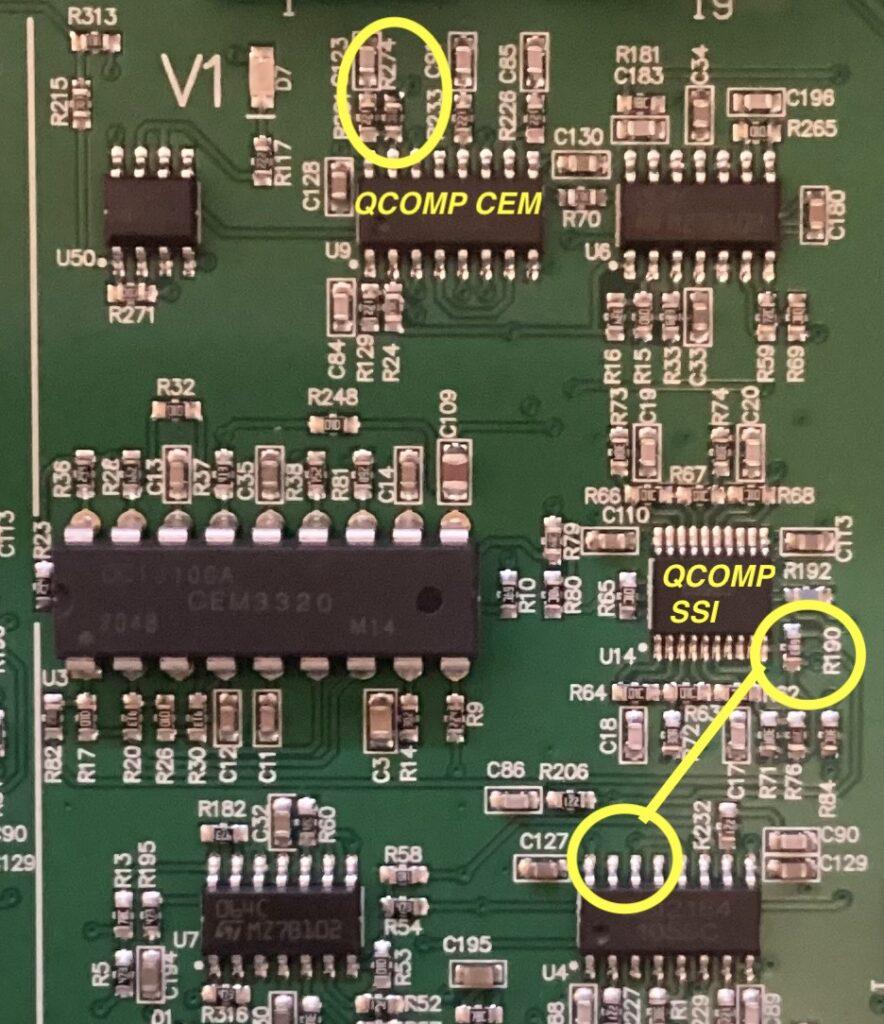
Augmented QCOMP effect
You can bump up the maximum QCOMP effect. For the SSI filter decrease R190 from 51k to 27k-30k. For the CEM decrease R274 from 16,2K to around 10-12K.
SSI normal maximum QCOMP:
SSI increased maximum QCOMP:
CEM normal maximum QCOMP:
CEM increased maximum QCOMP:
Bandpass filter type for 2140/3320
This is done per simple filter pole mixing. In the following two examples I mixed a bit of -12db signal to the -24db output. More info below in the “huckepack” section. For CEM bandpass clip, scroll to top of page…
SSI LP/BP:
Single Voice Outputs

This is *not* the classic panorama modification, which, sorry, I find not highly efficient. With the special voice allocation system and only 5 voices, the P5 is somewhat destined to work as a techno pattern machine and deserves, IMO, a dedicated output per voice. With these you can of course also do your classic fixed panorama stuff but so much more…
Check next section for how this can be done – info on how to rewire the existing I/O will come soon. If you want to drill hols for additional sockets, that’s an option too, of course!
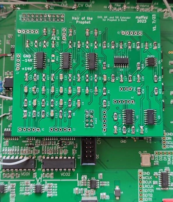
Hair of the Prophet Board
This is an extension board for the 5 voice (key, module) version that adds the following features to your Prophet 5 A) Single Voice Outputs that are also level controlled by main volume knob and automatically muted during the tuning procedure, B) switch for adding TRIANGLE A to the VCO A mix, C) switchable bandpass response for the CEM3320 filter.
The schematic (current version is 14 August 2023, V1_8) is here:
And the BOM is here (part links are examples only, so that you get an idea which component size/type): HAIROFTHEPROPHET_BOM. The gerber files for PCB production can be accessed here (NB this is a noncommerical product under Creative Commons License, i.e. for personal use only).
Quick circuit discussion:
If you install extra output sockets for the single voice outputs, you do not need to cut any trace of the existing circuitry. The TRI on VCO A and bandpass mods are simply wired onto the existing circuitry, so you can reverse everything in teh future, if desired.
TRI VCO switch on/off and bandpass VCF on/off settings cannot be stored per patch as I did not want to lose any existing feature of the Prophet 5. The TRI wave of VCO A is on level with that of VCO B, so when both are on full volume, you get some slightly overdriven signal on account of the filter input overloading. This happens with the other waveforms too, actually, we simply don’t hear the overdrive that well as we do with triangle waves. I thought being on level with VCO B is more important because you can simply dial things back a bit in the signal mixer. (In case you don’t like this and don’t mind TRI on VCO A being a tad quieter, exchange R1, R11, R19, R25, and R33 with 33k resistors).
Bandpass mode on the 3320 filter, on the other hand, has quite a bit more volume than the lowpass. This is because filter pole mixing is done by simply adding -12db signal (the -12db output is mixed together with the -24db output, so that phase cancellations make a bandpass response). Levelling things more would have meant being more invasive/cutting traces etc. As is, the signal level of the bandpass response does not cause any clipping in the VCA, so all you need to consider is that there’s a bit more whack and smack when you flip that switch. This responds very nicely to QCOMP and of course velocity on the filter env depth!
Here’s some quick and dirty demo of TRI and bandpass mods on the board…
And another single voice out demo…
That much for now – shoot us a message if you have questions/comments.