

https://www.synthxl.com/wp-content/uploads/2019/01/Roland-sh-5-service-notes.pdf
https://www.sequencer.de/synthesizer/threads/roland-sh-5-und-aehnliche-modifikationen.170760
https://modwiggler.com/forum/viewtopic.php?p=4256398
The What?
This is how the MS5 (modded) can sound…
And a dirty one…
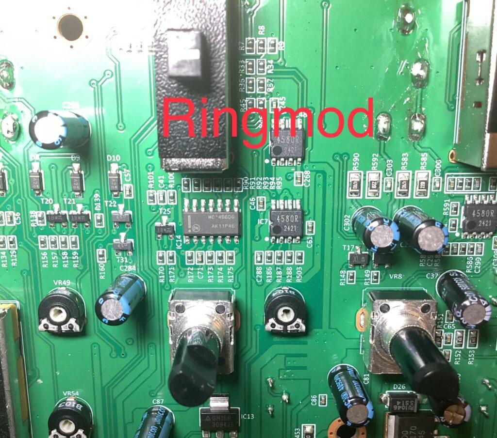
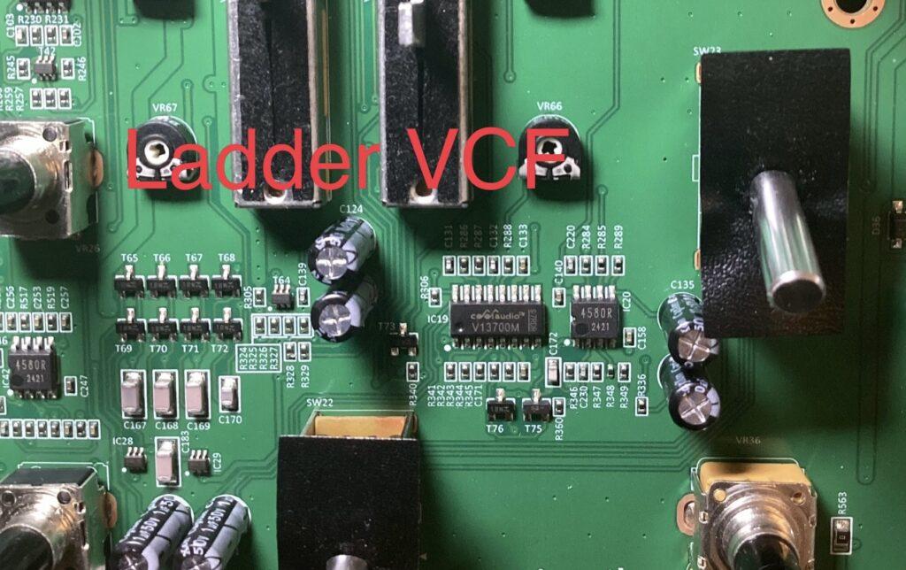
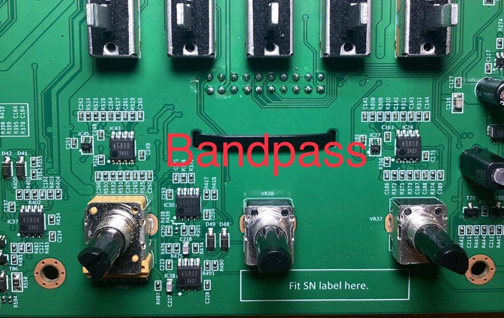
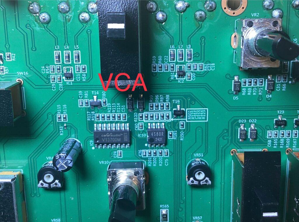
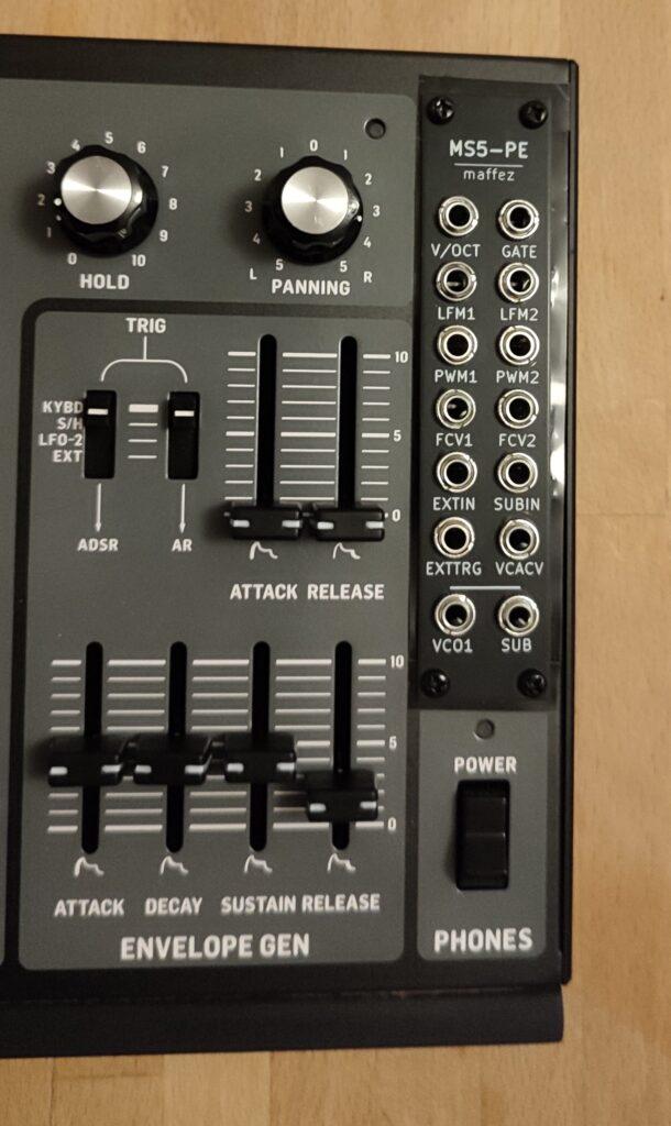
Teardown
See also here: https://imgur.com/a/xnSjJjT
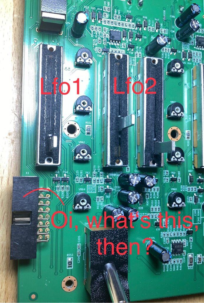
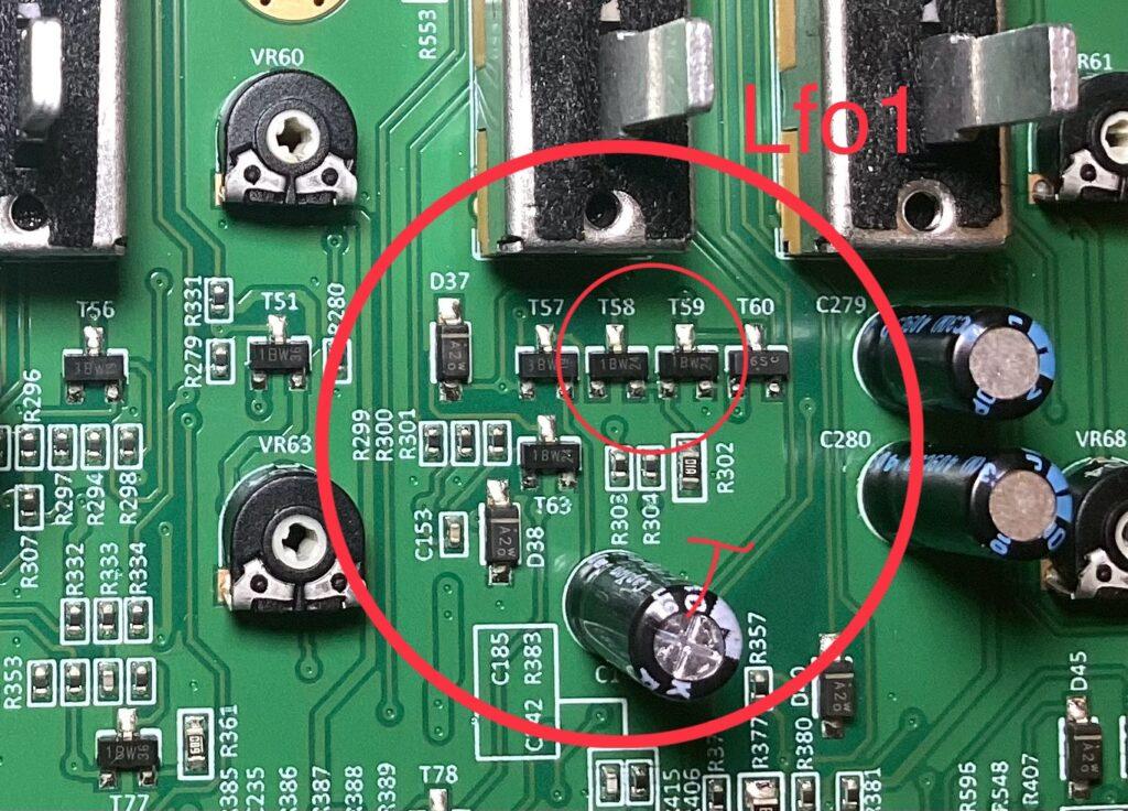
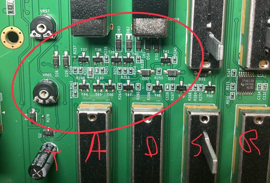
Notable differences to SH-5/first impressions: instead of Programmable Unijunction Transistors in LFO1 and ADSR, there are simple added transistors (see markings below); at front of AR and Fixed Envelope (I wrongly wrote “Gate” sometimes in the pics) there is a comparator IC we don’t find in the SH-5. Yet, the setup is not quite well chosen in terms of extreme level differences between ADSR, AR and Fixed Envelope (which could have been adjusted quite easily). Portamento, transpose and tune knob (on the left hand controller) are digital and partly wonky). Removing the LHC prevents you fron playing the SH per midi, but you can still use it as a CV-Gate-Driven Module, which is what I am going for. The headphones amp bites your ears off above 5% fader travel.
Modifications
I will document more in the coming weeks, but here are some for starters.
CV points
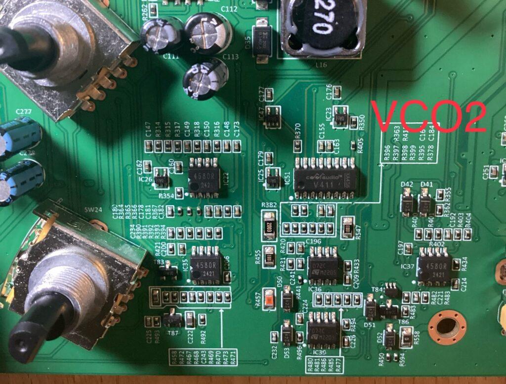
Linear FM: use an input socket, then go 100nf capacitor and 150k resistor in series. Connect the resistor to IC201, PIN2 for VCO1 LFM and/or IC37, PIN2 for VCO2 LFM.
VCO outputs: via 1k resistor to selected wave rotary switch pin. The “selected wave” pin of your rotary switch is here: look at the wave select switch, which is diagonal. Right hand side uppermost pin is the selected wave. You can also tap SAW and TRI individually, but the VCO setup is such that you don’t get square/PW unless that is the selected waveform.
PWM inputs: connect input sockets via 100k resistors to the following points (there are through vias on the back of the PCB, which might be easier to solder onto: VCO1 terminal of R411 that faces away from IC201; VCO2 terminal of R402 that faces away from IC37.
Cutoff Control CV (multi VCF): input socket via 100k reistor to IC15, PIN6.
VCA CV: input socket via 150k resistor to IC 10, PIN6.
LFO MODIFICATIONS
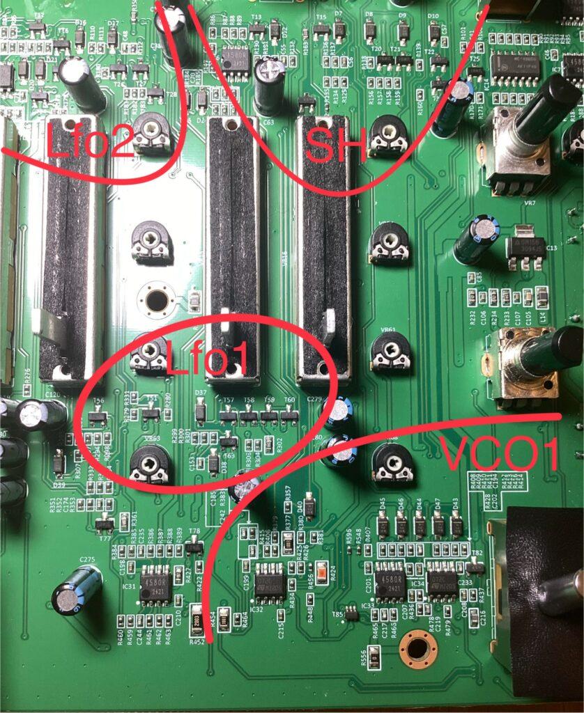
LFO1 RESET ON GATE ON deactivated: you can make LFO1 free running by pulling the base of T63 to ground. If you want to be able to alternate between reset/free running, use a SPDT switch.
LFO2 RESET ON GATE ON deactivated: you can make LFO1 free running by pulling the cathode of D15 to ground. If you want to be able to alternate between reset/free running, use a SPDT switch.
Modulation Bus Changes
This is the shizznizz… Replace rising and falling ramp LFO2 with VCO2 output: remove R145 and R179 (100 ohm each) and connect the selected VCO2 wave output via a 1k resistor to (as seen from the front) bottom terminal of where R145 used to be and top terminal of where R179 used to be. The selected wave of VCO2 now feeds into the mod buss and is available for VCO XMOD, filter FM, amplitude modulation, PWM at audio rate for VCO1 – each of these with individual depth control as per MOD dials. Super easy and turns your MS into a modern synthesizer…
Filter MODS
Adjust level of BP and HP in multi VCF: the multi VCF is louder on low pass setting than BP or HP. Simply wire a 3k resistor between IC20, pin2 and ground. Here’s an A/B:
Adjust VCF mod depth: change R220 (that’s R524 on the Roland) from 8.2k to 15k. I like it better that way.
Increase BPF resonance: wire a 2k-3k resistor between ground and resonance potentiometer PIN3 (rightmost as seen from the front).
Cutoff control for the BPF: this is advanced stuff and requires you to build a little sub PCB. The cutoff pot need to be replaced with a fitting A100K but you have to keep the pin holes on the PCB free. The sub PCB linked below offers more, but if you’re only after cutoff CV, then simply leave the sub osc and portamento circuit vacant.
This may look not much first, but with just a little imagination and an extra resistor or two, you can add keytracking, pos/neg env, lfo etc. On my own unit, I send the complete modulation signal sum of the main vcf to a bipolar pot that’s normalled through an input socket. This way, I can have the filter delta between both vcfs modulated for vowel fun 🙂
NB – part numbers for where to connect what in my schematic refer to SH-5 original, yet transferring them should be easy.
Envelope MODS
The sluggish AR is already a thing on the Roland, yet (as an SH5 owner stated after comparing ), it’s kinda worse on the MS5. That’s weird, to put it mildly, since Behringer took extra steps to make sure the GATE out and GATE in setups are compliant with modern Eurorack gear. Would have been so super easy to rectify that meh aspect. An though it’s really Behringer’s job do change this or not in future units, here’s an easy fix. if you implement it successfully, please donate a fiver to the Women’s Audio Mission or Uli B shall haunt you in your sleep forever…
Cable trick: plug gate out to TRG in (3,5 to 6,3 adapter cable needed) and set AR TRIG to “EXT”.
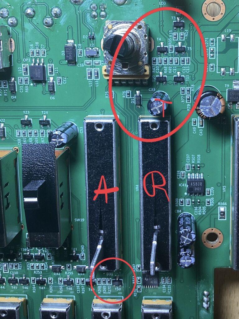
Fixed AR BOOST: Wire a 1N4148 diode from the top terminal (collector) of T1 (near the Gate output socket) to IC 40, PIN1 (cathode goes to IC40, Pin1). Wire another 1N4148 from ground (anode) to the top terminal (collector) of T1 to protect that one from negative voltage. This makes midi gate and internal keyboard gate blast into the AR circuitry, which ups the AR level and speeds up the capacitor charge time. If you want to use this effect when using the GATE in socket too, simply wire a cable from the second uppermost solder blob of the GATE IN socket to the top terminal of R6.
(Why and what? – the AR is driven by a simple transistor that pushes the timing capacitor in relation to the incoming gate level. Later designs used comparators (like the one Behringer added, but in a more sensible manner) or transistor switches (see Arp Odyssey versus the shambolic 2600 AR). Oddly, B used a transistor switch for the gate output, making sure external devices are gated well, and added a comparator IC to make sure incoming gates work, but kinda to the result that AR is even more sluggish…
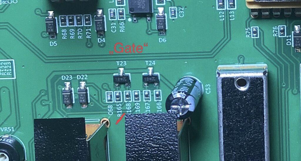
Faster Fixed Envelope: replace C53 (1uf electrolytic cap) with 47nf film box or ceramic cap. That gives you some snappier response that doesn’t click. On the SH101 this would be the “GATE” setting.
More Fixed Envelope Impact: wire a 1k resistor between the cathode of D23 and the base of T24.
more soon!