
Some two clips, partly processed
Interior Design
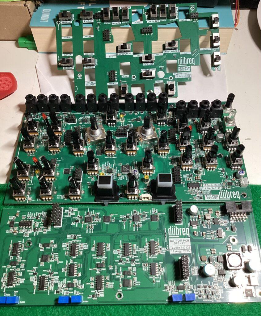
As you see, you get a sandwich of three PCBs. The lower one contains all the filter and VCA circuits, as well as some IC switches. The latter is good since this means audio signals do not need to travel that far. The middle PCB hosts a CPU (for the envs and sample and holds, I guess), the PT delay chip, and most control elements. The uppermost PCB is just switches.
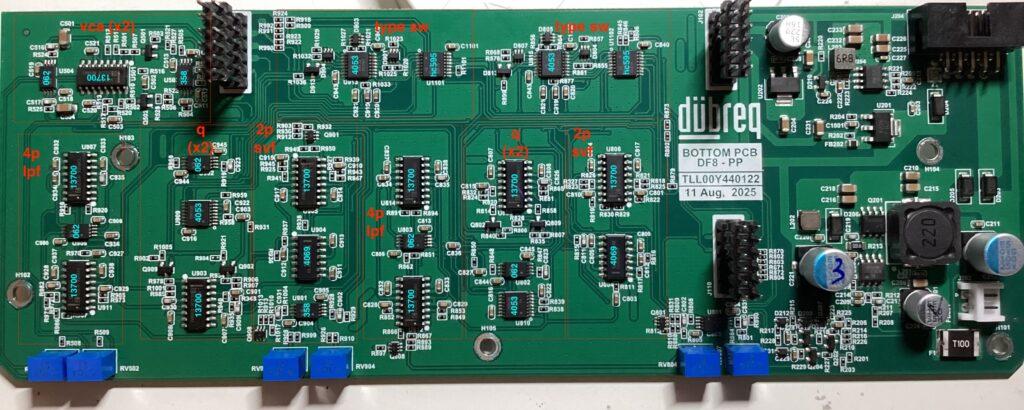
This is the VCF and VCA part (plus power supply). More later, and this initial info is only based on visual inspection, not probing/measuring: the 12db SVF is inspired by the WASP VCF (LM13700 OTA + 4069 Hexinverter buffers), and the 24db low pass is a simple 4x OTA cascade. Resonance is done with another 13700 OTA, which means CV for resonance can be implemented easily, and the final VCAs, again, are LM13700 OTAs. Filter modes are switched per 4053 IC switches. Nothing exotic but nothing shank either.
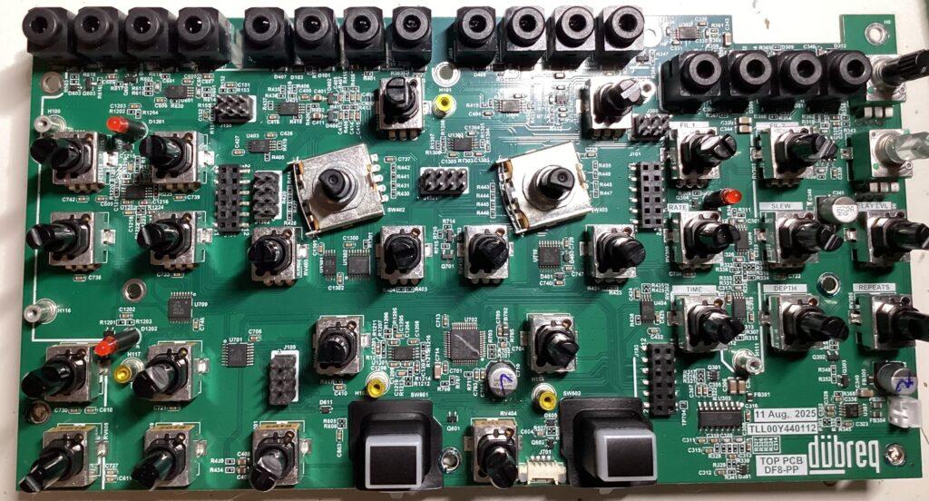
Middle PCB with heckloads of connectors and mostly op amps (TL062 and LM358), more 4053 multiplexers, the PT2399 delay IC, and a STM32L0 computationator (lol). Especially that one, the LM4580 opa on the main out, and the jack socket types whisper “Berhinger”, but it clearly reads dübreq on the PCB, so that’s what it is, then. Again, a lot to test out, like CV over envelope stage times etc.
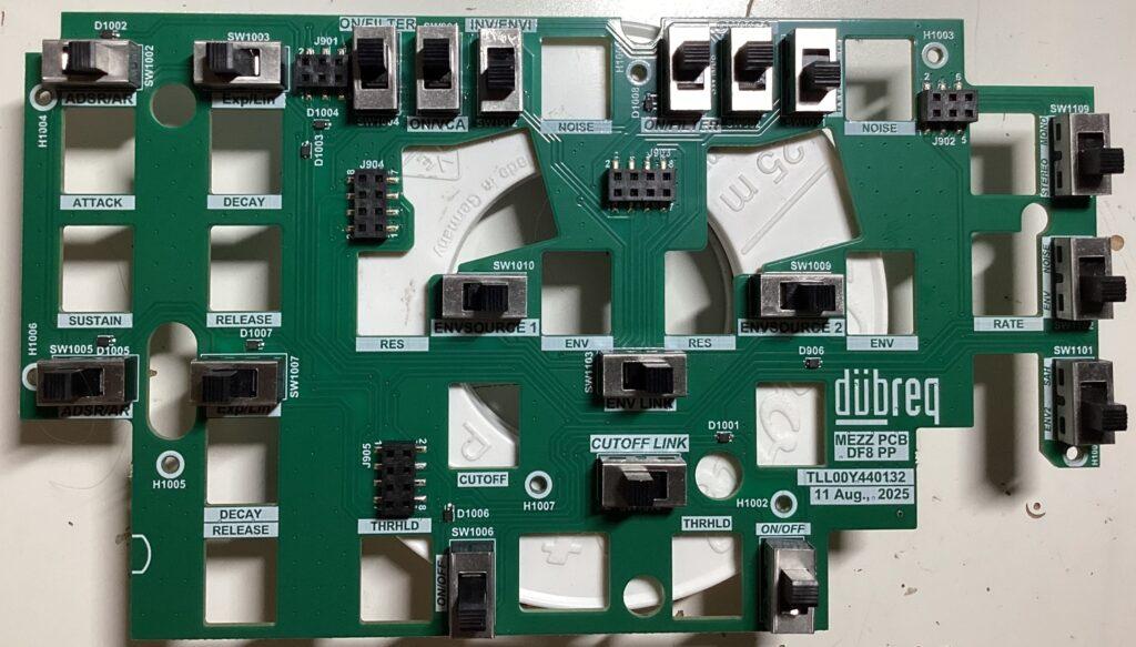
Finally, the top layer of our filter Reuben. I’d bodly call this a switch PCB… No audio passing through these, which is great in reducing the overall noise floor. Not that these filters are the most hifi or tamest, though, but I like their character!
Modifications
There is a number of things I want to do with this box, but a couple things for starters…
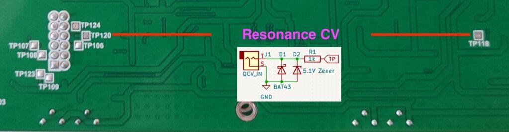
Resonance CV input: resonance on the four individual filter circuits is done per VCA (LM13700 OTA), but the DF-8 only has manual resonance control. If you want external QCV inputs, you can simply use some little protection circuits (two diodes clipping incoming voltages between zero and 5.1 volts and a resistor), which you can piggyback onto TP120 and TP118 respectively.
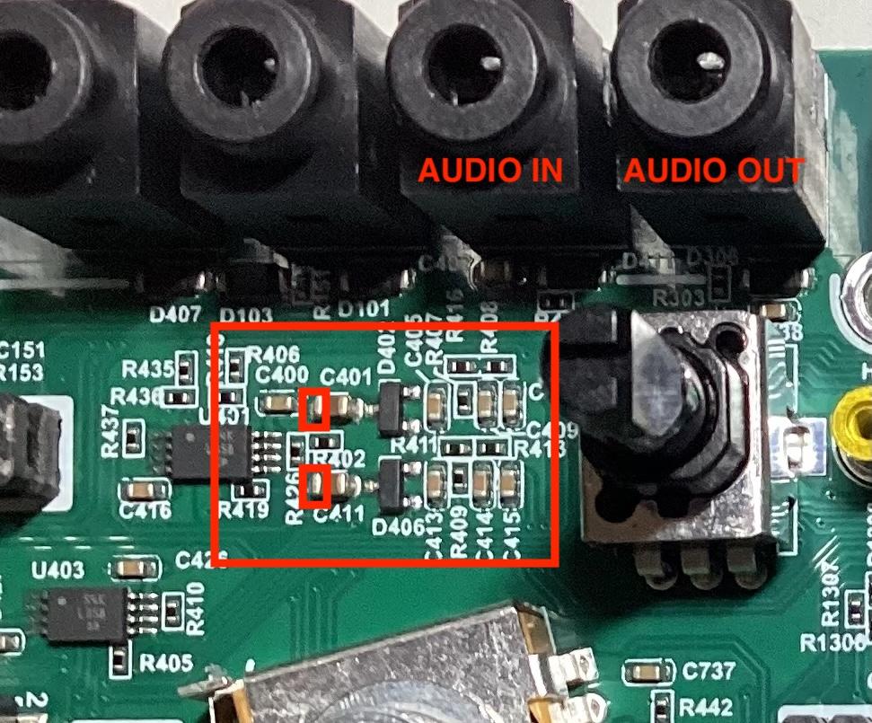
INSERT for the Envelope trigger per audio detection: having audio trigger the envelopes is awesome! Better, though, if you can also use an audio signal other than the one processed for triggering. This way, you can do cool things like sidechaining or signal replacement stuff as well. The mod is easy but needs a bit of experience with desoldering smd caps as you need to lift C401 and C411 and put them partially back in again. We need to break the left hand connection of these caps, as marked on the picture below, so best desolder the caps and then solder them back in so that one end connects to D402 and D406 respectively and the other terminal sticks out into the open air. We then connect a switched audio input socket (NC lug to the freed PCB terminal of C401/C411 at the left hand, and tip lug to the actual cap terminal sticking out into the open). This way, the swicthed cap rtains the audio connection between teh normal audio in and the detection circuit until you plug a cable with another signal in (which then makes the envelopes trigger). Since the caps and the diodes are there for protection, you needn’t worry about signal levels, as long as you remain within the eurorack range.
Inserts for the final mixer (Filter I, Filter II): This one is easy too and lets you use the mixer, including the delay, with other signals as well. The mixer post-level potentiometers is protected enough so that you needn’t worry about buffers. Simply lift the rightmost pin (as seen from component side) of Filter I and Filter II level pot out of their PCB terminals and insert a switched jack socket. PCB terminal goes to NC lug and tip lug of the socket goes to the lifted out potentiometer pin. (If you wanna play extra safe, insert a 10uf cap between tip lug of your socket and the potentiometer pin.) Nothing plugged into the socket = business as usual, signal plugged = OMG, an extra FX mixer!
That much for now – more soon!